| [ < ] | [ > ] | [ << ] | [ Up ] | [ >> ] | [Top] | [Contents] | [Index] | [ ? ] |
The following example, which forms the basis of the example file ‘mbuff.csp’, provides a more interesting and realistic case-study than the one seen earlier.
| 1.4.1 Multiplexed buffer example |
| [ < ] | [ > ] | [ << ] | [ Up ] | [ >> ] | [Top] | [Contents] | [Index] | [ ? ] |
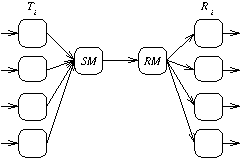
Consider the problem of transmitting a number of message streams over a single data connection. We can share a single channel between the streams by adding multiplexing and demultiplexing processes, as in figure 1.
Figure 1: Multiplexed Buffers
This solution is inadequate if we wish to synchronise the sending and receiving processes because the multiplexing introduces additional buffering into the channel. Typical specifications on such a system might include the need to ensure that one lane does not interfere with another, and that there is a bound on the amount of buffering introduced by the network. We therefore insist that the connection between each sender and the corresponding receiver acts as if it were a simple single place buffer like COPY (see section Simple buffer example). The combination of N channels then behaves like the unsynchronised parallel composition of N simple buffers.
COPYj = leftj?x rightj!x
SPEC = COPYi
Our requirement on the multiplexed system is that it refines this SPEC process. To avoid the introduction of extra buffering and interaction where one channel clogs the system when its receiver does not pick up messages soon enough, we introduce acknowledgement signals from the receivers to the senders as in the earlier example. This can also be multiplexed through a single channel, as shown in figure 2.
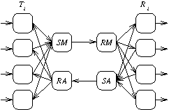
Figure 2: Multiplexed Buffers with Acknowledgement
The implementation will therefore consist of N transmitters (Ti), N receivers (Ri)and four processes which manage the forward and reverse channels: SM (Send Message) which multiplexes transmitted data and RM (Receive Message) which demultiplexes it, together with SA (Send Acknowledge) and RA (Receive Acknowledge) which perform similar functions for the acknowledgement channel. The system can be built up as follows:
INS =
LHS = INS (SM
RA)) \ X,
where X={|mux,admx|}
where left denotes the whole set of indexed channels
lefti,
for i 1..N.Similarly mux, dmx, amux, admx and
right also denote sets of indexed channels.
1..N.Similarly mux, dmx, amux, admx and
right also denote sets of indexed channels.
OUTS =
RHS = OUTS where X={|dmx,amux|}
SYSTEM = LHS where X={|mess,ack|}
If this implementation is correct, then we will have
SPECSYSTEM
Establishing this using traces refinement shows that the multiplexed buffers perform no incorrect events. Using failures-divergence refinement will show that they cannot diverge, and cannot refuse input on any of the individual channels which is empty nor refuse output an any channel which is full. Failures refinement alone could show that the buffers never get into a stable state that can refuse a set not permitted by the specification, but would not exclude divergence — which obviously looks like refusal from the outside.
This example is explored further in the tutorial (see section Tutorial), and a listing of the FDR2-compatible source can be found in Multiplexed Buffer Script.
| [ < ] | [ > ] | [ << ] | [ Up ] | [ >> ] |
This document was generated by Phil Armstrong on May 17, 2012 using texi2html 1.82.